Initialise the devices state. More...
#include "inc/freeEMS.h"#include "inc/interrupts.h"#include "inc/utils.h"#include "inc/commsISRs.h"#include "inc/pagedLocationBuffers.h"#include "inc/init.h"#include "inc/decoderInterface.h"#include "inc/xgateVectors.h"#include <string.h>
Go to the source code of this file.
Macros | |
| #define | INIT_C |
Functions | |
| void | init () |
| The main top level init. | |
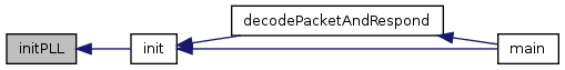
| void | initPLL () |
| Set the PLL clock frequency. | |
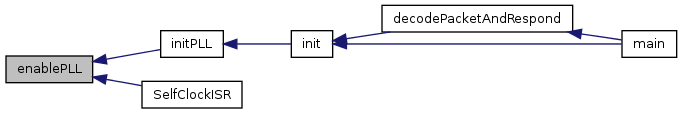
| void | enablePLL () |
| Switch to using PLL. | |
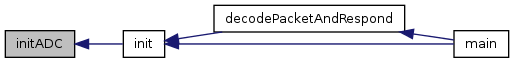
| void | initADC () |
| Set up the analogue inputs. | |
| void | initPWM () |
| Set up the PWM module from configuration. | |
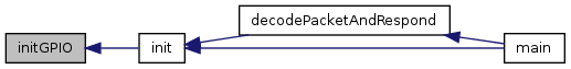
| void | initGPIO () |
| Set up all the pin states as per configuration, but protect key states. | |
| void | initLookupAddresses () |
| Buffer lookup tables addresses. | |
| void | initFuelAddresses () |
| Buffer fuel tables addresses. | |
| void | initPagedRAMFuel (void) |
| Copy fuel tables to RAM. | |
| void | initTimingAddresses () |
| Buffer timing tables addresses. | |
| void | initPagedRAMTime () |
| Copy timing tables to RAM. | |
| void | initTunableAddresses () |
| Buffer tunable tables addresses. | |
| void | initPagedRAMTune () |
| void | initAllPagedAddresses () |
| Buffer addresses of paged data. | |
| void | initAllPagedRAM () |
| Copies paged flash to RAM. | |
| void | initVariables () |
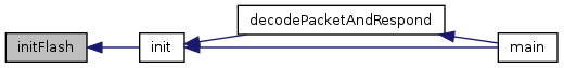
| void | initFlash () |
| Flash module setup. | |
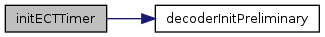
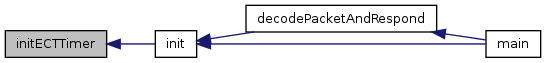
| void | initECTTimer () |
| void | initPITTimer () |
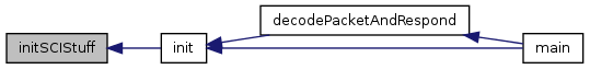
| void | initSCIStuff () |
| void | initConfiguration () |
| void | initInterrupts () |
Detailed Description
Initialise the devices state.
Setup, configure and initialise all aspects of the devices state including but not limited to:
- Setup the bus clock speed
- Configuration based variable initialisation
- I/O register behaviour and initial state
- Configure and enable interrupts
- Copy tunable data up to RAM from flash
- Configure peripheral module behaviour
Definition in file init.c.
Macro Definition Documentation
Function Documentation
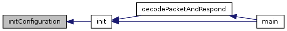
| void init | ( | void | ) |
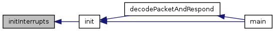
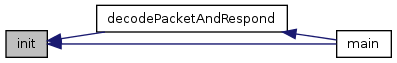
The main top level init.
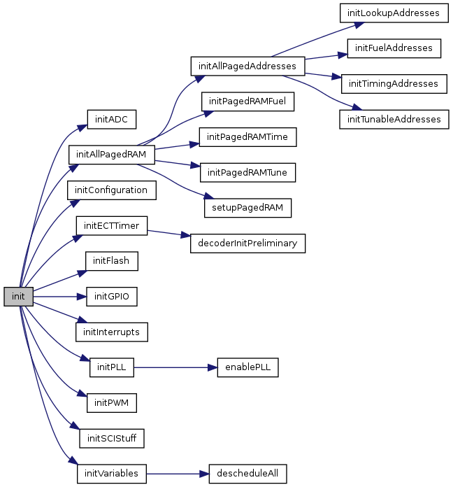
The main init function to be called from main.c before entering the main loop. This function is simply a delegator to the finer grained special purpose init functions.
Definition at line 61 of file init.c.
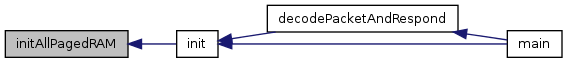
References ATOMIC_END, ATOMIC_START, initADC(), initAllPagedRAM(), initConfiguration(), initECTTimer(), initFlash(), initGPIO(), initInterrupts(), initPLL(), initPWM(), initSCIStuff(), and initVariables().
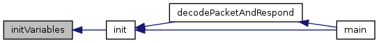
Referenced by decodePacketAndRespond(), and main().
| void initPLL | ( | ) |
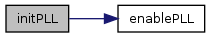
Set the PLL clock frequency.
Set the Phase Locked Loop to our desired frequency (80MHz) and enable PLL.
Definition at line 91 of file init.c.
References CLKSEL, enablePLL(), PLLCTL, PLLDIVISOR, PLLMULTIPLIER, PLLOFF, PLLON, PLLSELOFF, REFDV, and SYNR.
Referenced by init().
| void enablePLL | ( | void | ) |
Switch to using PLL.
Switch to using PLL for clock (40MHz bus speed). Interrupt is enabled elsewhere.
Note: Requires busy wait loop, only for init and emergency use.
- Todo:
- Should be limited, and have break out with error code and fall back mechanism.
Definition at line 108 of file init.c.
References CLKSEL, CRGFLG, PLLLOCK, and PLLSEL.
Referenced by initPLL(), and SelfClockISR().
| void initADC | ( | ) |
Set up the analogue inputs.
Definition at line 124 of file init.c.
References ATD0CTL2, ATD0CTL3, ATD0CTL4, ATD0CTL5, ATD1CTL0, ATD1CTL2, ATD1CTL3, ATD1CTL4, and ATD1CTL5.
Referenced by init().
| void initPWM | ( | ) |
Set up the PWM module from configuration.
Definition at line 154 of file init.c.
References fixedConfigs2, fixedConfig2::inputOutputSettings, PWMCAE, inputOutputSetting::PWMCenterAlign, PWMCLK, inputOutputSetting::PWMClock, inputOutputSetting::PWMClockPrescaler, inputOutputSetting::PWMControl, PWMCTL, PWMDTY0, PWMDTY1, PWMDTY2, PWMDTY3, PWMDTY4, PWMDTY5, PWMDTY6, PWMDTY7, PWME, inputOutputSetting::PWMEnable, inputOutputSetting::PWMInitialDuty0, inputOutputSetting::PWMInitialDuty1, inputOutputSetting::PWMInitialDuty2, inputOutputSetting::PWMInitialDuty3, inputOutputSetting::PWMInitialDuty4, inputOutputSetting::PWMInitialDuty5, inputOutputSetting::PWMInitialDuty6, inputOutputSetting::PWMInitialDuty7, PWMPER0, PWMPER1, PWMPER2, PWMPER3, PWMPER4, PWMPER5, PWMPER6, PWMPER7, inputOutputSetting::PWMPeriod0, inputOutputSetting::PWMPeriod1, inputOutputSetting::PWMPeriod2, inputOutputSetting::PWMPeriod3, inputOutputSetting::PWMPeriod4, inputOutputSetting::PWMPeriod5, inputOutputSetting::PWMPeriod6, inputOutputSetting::PWMPeriod7, PWMPOL, inputOutputSetting::PWMPolarity, PWMPRCLK, inputOutputSetting::PWMScalerA, inputOutputSetting::PWMScalerB, PWMSCLA, and PWMSCLB.
Referenced by init().

| void initGPIO | ( | ) |
Set up all the pin states as per configuration, but protect key states.
Definition at line 190 of file init.c.
References BIT6, BIT7, DDRA, DDRB, DDRC, DDRD, DDRE, DDRH, DDRJ, DDRK, DDRM, DDRP, DDRS, DDRT, fixedConfigs2, fixedConfig2::inputOutputSettings, NBIT5, NBIT6, PORTA, PORTB, PORTC, PORTD, inputOutputSetting::PortDirectionA, inputOutputSetting::PortDirectionB, inputOutputSetting::PortDirectionC, inputOutputSetting::PortDirectionD, inputOutputSetting::PortDirectionE, inputOutputSetting::PortDirectionH, inputOutputSetting::PortDirectionJ, inputOutputSetting::PortDirectionK, inputOutputSetting::PortDirectionM, inputOutputSetting::PortDirectionP, inputOutputSetting::PortDirectionS, PORTE, PORTH, inputOutputSetting::PortInitialValueA, inputOutputSetting::PortInitialValueB, inputOutputSetting::PortInitialValueC, inputOutputSetting::PortInitialValueD, inputOutputSetting::PortInitialValueE, inputOutputSetting::PortInitialValueH, inputOutputSetting::PortInitialValueJ, inputOutputSetting::PortInitialValueK, inputOutputSetting::PortInitialValueM, inputOutputSetting::PortInitialValueP, inputOutputSetting::PortInitialValueS, PORTJ, PORTK, PORTM, PORTP, PORTS, and PORTT.
Referenced by init().
| void initLookupAddresses | ( | ) |
Buffer lookup tables addresses.
Save pointers to the lookup tables which live in paged flash.
Definition at line 229 of file init.c.
References CHTTransferTable, CHTTransferTableLocation, IATTransferTable, IATTransferTableLocation, MAFTransferTable, MAFTransferTableLocation, TestTransferTable, and TestTransferTableLocation.
Referenced by initAllPagedAddresses().

| void initFuelAddresses | ( | ) |
Buffer fuel tables addresses.
Save pointers to the fuel tables which live in paged flash.
Definition at line 241 of file init.c.
References AirflowTableFlash, AirflowTableFlash2, AirflowTableFlash2Location, AirflowTableFlashLocation, LambdaTableFlash, LambdaTableFlash2, LambdaTableFlash2Location, LambdaTableFlashLocation, VETableMainFlash, VETableMainFlash2, VETableMainFlash2Location, VETableMainFlashLocation, VETableSecondaryFlash, VETableSecondaryFlash2, VETableSecondaryFlash2Location, and VETableSecondaryFlashLocation.
Referenced by initAllPagedAddresses().

| void initPagedRAMFuel | ( | void | ) |
Copy fuel tables to RAM.
Initialises the fuel tables in RAM by copying them up from flash.
Definition at line 258 of file init.c.
References AirflowTableFlash2Location, AirflowTableFlashLocation, LambdaTableFlash2Location, LambdaTableFlashLocation, RPAGE, RPAGE_FUEL_ONE, RPAGE_FUEL_TWO, VETableMainFlash2Location, VETableMainFlashLocation, VETableSecondaryFlash2Location, and VETableSecondaryFlashLocation.
Referenced by initAllPagedRAM().

| void initTimingAddresses | ( | ) |
Buffer timing tables addresses.
Save pointers to the timing tables which live in paged flash.
Definition at line 277 of file init.c.
References IgnitionAdvanceTableMainFlash, IgnitionAdvanceTableMainFlash2, IgnitionAdvanceTableMainFlash2Location, IgnitionAdvanceTableMainFlashLocation, IgnitionAdvanceTableSecondaryFlash, IgnitionAdvanceTableSecondaryFlash2, IgnitionAdvanceTableSecondaryFlash2Location, IgnitionAdvanceTableSecondaryFlashLocation, InjectionAdvanceTableMainFlash, InjectionAdvanceTableMainFlash2, InjectionAdvanceTableMainFlash2Location, InjectionAdvanceTableMainFlashLocation, InjectionAdvanceTableSecondaryFlash, InjectionAdvanceTableSecondaryFlash2, InjectionAdvanceTableSecondaryFlash2Location, and InjectionAdvanceTableSecondaryFlashLocation.
Referenced by initAllPagedAddresses().

| void initPagedRAMTime | ( | ) |
Copy timing tables to RAM.
Initialises the timing tables in RAM by copying them up from flash.
Definition at line 294 of file init.c.
References IgnitionAdvanceTableMainFlash2Location, IgnitionAdvanceTableMainFlashLocation, IgnitionAdvanceTableSecondaryFlash2Location, IgnitionAdvanceTableSecondaryFlashLocation, InjectionAdvanceTableMainFlash2Location, InjectionAdvanceTableMainFlashLocation, InjectionAdvanceTableSecondaryFlash2Location, InjectionAdvanceTableSecondaryFlashLocation, RPAGE, RPAGE_TIME_ONE, and RPAGE_TIME_TWO.
Referenced by initAllPagedRAM().

| void initTunableAddresses | ( | ) |
Buffer tunable tables addresses.
Save pointers to the tunable tables which live in paged flash and their sub-sections too.
Definition at line 314 of file init.c.
References SmallTables1::blendVersusRPMTable, blendVersusRPMTable2Location, blendVersusRPMTableLocation, SmallTables1::dwellDesiredVersusVoltageTable, dwellDesiredVersusVoltageTable2Location, dwellDesiredVersusVoltageTableLocation, SmallTables1::dwellVersusRPMTable, dwellVersusRPMTable2Location, dwellVersusRPMTableLocation, SmallTables1::engineTempEnrichmentTableFixed, engineTempEnrichmentTableFixed2Location, engineTempEnrichmentTableFixedLocation, SmallTables1::engineTempEnrichmentTablePercent, engineTempEnrichmentTablePercent2Location, engineTempEnrichmentTablePercentLocation, SmallTables1::filler, SmallTables2::filler, SmallTables3::filler, SmallTables4::filler, fillerA2Location, fillerALocation, fillerB2Location, fillerBLocation, fillerC2Location, fillerCLocation, fillerD2Location, fillerDLocation, SmallTables1::injectorDeadTimeTable, injectorDeadTimeTable2Location, injectorDeadTimeTableLocation, SmallTables2::loggingSettings, loggingSettings2Location, loggingSettingsLocation, SmallTables2::perCylinderFuelTrims, perCylinderFuelTrims2Location, perCylinderFuelTrimsLocation, SmallTables1::postStartEnrichmentTable, postStartEnrichmentTable2Location, postStartEnrichmentTableLocation, SmallTables1::primingVolumeTable, primingVolumeTable2Location, primingVolumeTableLocation, SmallTablesAFlash, SmallTablesAFlash2, SmallTablesAFlash2Location, SmallTablesAFlashLocation, SmallTablesBFlash, SmallTablesBFlash2, SmallTablesBFlash2Location, SmallTablesBFlashLocation, SmallTablesCFlash, SmallTablesCFlash2, SmallTablesCFlash2Location, SmallTablesCFlashLocation, SmallTablesDFlash, SmallTablesDFlash2, SmallTablesDFlash2Location, and SmallTablesDFlashLocation.
Referenced by initAllPagedAddresses().

| void initPagedRAMTune | ( | ) |
Definition at line 370 of file init.c.
References RPAGE, RPAGE_TUNE_ONE, RPAGE_TUNE_TWO, SmallTablesAFlashLocation, SmallTablesBFlashLocation, SmallTablesCFlashLocation, and SmallTablesDFlashLocation.
Referenced by initAllPagedRAM().

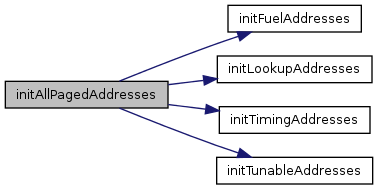
| void initAllPagedAddresses | ( | ) |
Buffer addresses of paged data.
Save the paged memory addresses to variables such that we can access them from another paged block with no warnings.
If you try to access paged data from the wrong place you get nasty warnings. These calls to functions that live in the same page that they are addressing prevent those warnings.
- Note
- Many thanks to Jean Bélanger for the inspiration/idea to do this!
Definition at line 404 of file init.c.
References initFuelAddresses(), initLookupAddresses(), initTimingAddresses(), and initTunableAddresses().
Referenced by initAllPagedRAM().

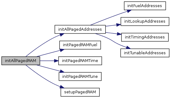
| void initAllPagedRAM | ( | ) |
Copies paged flash to RAM.
Take the tables and config from flash up to RAM to allow live tuning.
For the main tables and other paged config we need to adjust the RPAGE value to the appropriate one before copying up.
This function is simply a delegator to the ones for each flash page. Each one lives in the same paged space as the data it is copying up.
Definition at line 424 of file init.c.
References initAllPagedAddresses(), initPagedRAMFuel(), initPagedRAMTime(), initPagedRAMTune(), setupPagedRAM(), and TRUE.
Referenced by init().
| void initVariables | ( | ) |
Definition at line 440 of file init.c.
References ADCBuffers, ADCBuffers0, ADCBuffers1, ADCBuffersRecord, coreStatusA, CoreVars, CoreVars0, DerivedVars, DerivedVars0, descheduleAll(), ectMainControlRegisters, ectMainTimeRegisters, FUEL_PUMP_PRIME, TC2_ADDR, TC3_ADDR, TC4_ADDR, TC5_ADDR, TC6_ADDR, TC7_ADDR, TCTL1_ADDR, TCTL2_ADDR, ticksPerDegree, ticksPerDegree0, ticksPerDegree1, and ticksPerDegreeRecord.
Referenced by init().

| void initFlash | ( | ) |
Flash module setup.
Initialise configuration registers for the flash module to allow burning of non-volatile flash memory from within the firmware.
The FCLKDIV register can be written once only after reset, thus the lower seven bits and the PRDIV8 bit must be set at the same time.
We want to put the flash clock as high as possible between 150kHz and 200kHz
The oscillator clock is 16MHz and because that is above 12.8MHz we will set the PRDIV8 bit to further divide by 8 bits as per the manual.
16MHz = 16000KHz which pre-divided by 8 is 2000kHz
2000kHz / 200kHz = 10 thus we want to set the divide register to 10 or 0x0A
Combining 0x0A with PRDIV8 gives us 0x4A (0x0A | 0x40 = 0x4A) so we use that
- Note
- If you use a different crystal lower than 12.8MHz PRDIV8 should not be set.
- Warning
- If the frequency you end up with is outside 150kHz - 200kHz you may damage your flash module or get corrupt data written to it.
Definition at line 499 of file init.c.
References ACCERR, FCLKDIV, FPROT, FSTAT, and PVIOL.
Referenced by init().
| void initECTTimer | ( | ) |
- Todo:
- TODO Take the configuration from the decoder (as is) and mask it such that it does not affect the 6 other channels. Take the the number of output channels required from configuration and configure that many as outputs Configure the balance in whatever way is specified in the GPIO configuration - allow second input to be reused as GPI only.
This stuff affects:
- TIE = 0x01 or 0x03, only. OC channels enabled as required and IC only for RPM/position.
- TIOS = nope, always 0xFC for 2 IC and 6 OC
- TCTL (1,2,3,4) 4 = 0x0? mask off high 4 bits and allow low 4 to come from decoder config/init
- PORTT = zeros, with balance from config
- DDRT = 0,1 inputs, or if unused by decoder, from config
Definition at line 507 of file init.c.
References decoderInitPreliminary(), ONES, PTPSR, TCTL1, TCTL2, TCTL3, TCTL4, TFLG, TFLGOF, TIE, TIOS, TSCR1, TSCR2, and ZEROS.
Referenced by init().
| void initPITTimer | ( | ) |
Definition at line 563 of file init.c.
| void initSCIStuff | ( | ) |
Definition at line 582 of file init.c.
References serialSetting::baudDivisor, fixedConfigs1, SCI0BD, SCI0CR1, SCI0CR2, and fixedConfig1::serialSettings.
Referenced by init().
| void initConfiguration | ( | ) |
Definition at line 626 of file init.c.
References bootFuelConst, fixedConfig1::engineSettings, fixedConfigs1, fixedConfigs2, engineSetting::injectorFlow, masterFuelConstant, engineSetting::perCylinderVolume, fixedConfig2::sensorRanges, engineSetting::stoichiometricAFR, TPSADCRange, sensorRange::TPSMaximumADC, and sensorRange::TPSMinimumADC.
Referenced by init().
| void initInterrupts | ( | ) |
Definition at line 649 of file init.c.
References AVIE, CRGFLG, CRGINT, IVBR, ONES, PIEH, PIFH, PLLLOCKIE, PLLLOCKIF, PPSH, RAMWPC, RTICTL, RTIE, RTIF, SCMIE, SCMIF, VREGCTRL, and ZEROS.
Referenced by init().